
Subject: Action Required – Drawing Discrepancy + ECO Request + Protection Setting Confirmation | CA-PEP01 SD Mega | SWBD#1 SEL-700G
Document Information
Project: PepsiCo Energy Storage Project – SDG&E Interconnection Compliance Support
Project ID: PJ2506-0008
Document Type: Technical Escalation / ECO Request
Document Ref: CA-PEP01-SD-SWBD1-ECO-001
Version: Rev. A
Date: May 4, 2026
Prepared by: Energize Solutions Inc.
Prepared for: Black & Veatch (B&V)
End Customer: PepsiCo
Utility: SDG&E
Subject: SWBD#1 SEL-700G Drawing Discrepancy, ECO Request, and Protection Setting Confirmation
Hi Utkarsh,
Following our technical review of the Ravenvolt SWBD#1 drawings (Rev B, January 2026), we have identified four items that require formal resolution before we can finalize the SEL-700G .RDB configuration file and proceed with commissioning. These items are documented with specific drawing references below.
We respectfully request that B&V coordinate with Ravenvolt to issue the necessary Engineering Change Order (ECO), and that B&V's Engineer of Record (EOR) provide the written confirmation noted in Item 3.
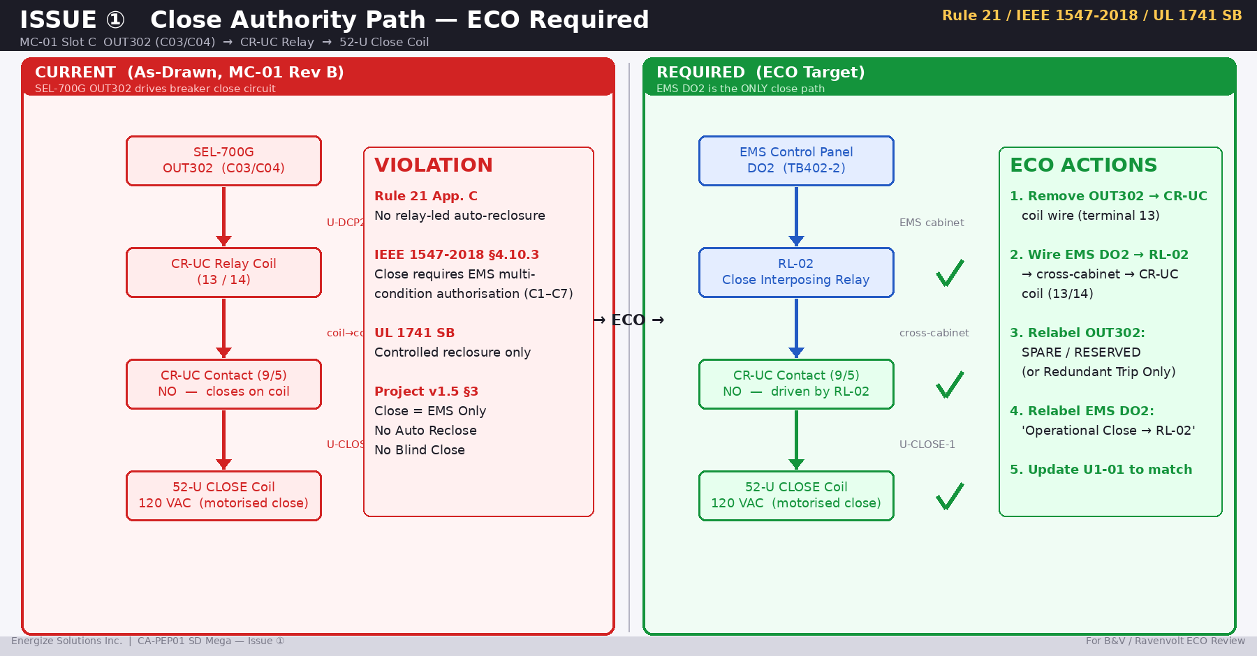
Item 1 — Critical Drawing Discrepancy: OUT301/OUT302 Function Labels vs. Actual Wiring (ECO Required)
Finding
A cross-reference review between drawing sheets MC-01 and U1-01 has identified a direct inconsistency in the labeled function of SEL-700G Slot C outputs OUT301 and OUT302.
Per MC-01 (SEL-700G Slot C Output Labels):
OUT301 (C01/C02) — Labeled: "52-U OPEN CB"
                 — Referenced: USED ON SHEET U1-01, C1

OUT302 (C03/C04) — Labeled: "52-U CLOSE CB"
                 — Referenced: USED ON SHEET U1-01, C1
                 — Connected to: CR-UC relay coil (terminals 13/14)
                                 via U-DCP2-2 / U-DCN2-2
Per U1-01 (Breaker Control Circuit — Actual Wiring):
Closing circuit (120VAC):
U-120L → M3 → CR-UC contact (terminals 9/5, NO)
       → U-CLOSE-1 → 52-U CLOSE coil (120VAC motorized close)

Tripping circuit (24VDC):
U-DCP1 → SYS-700G-C03 (OUT302, terminals C03/C04)
        → U-OPEN-1 → 52-U OPEN coil (24VDC shunt trip)
The Discrepancy
MC-01 labels OUT302 as "52-U CLOSE CB" and shows it driving the CR-UC relay coil, which is in the closing circuit.
U1-01 shows the physical terminal SYS-700G-C03 (which is OUT302) connected directly to U-OPEN-1, which feeds the 52-U OPEN (shunt trip) coil.
These two drawings describe OUT302 as performing opposite functions. This is a critical inconsistency that must be resolved before any .RDB configuration or field wiring proceeds.
Risk Assessment
Depending on which drawing reflects the actual intended design, one of the following conditions exists:
Scenario A — Labels incorrect, wiring correct (OUT302 = Trip):
The .RDB must configure OUT302 as a trip output, not a close output. The label "52-U CLOSE CB" on MC-01 is a documentation error that will cause incorrect field wiring assumptions during commissioning.
Scenario B — Labels correct, wiring inconsistent (OUT302 = Close):
The U1-01 wiring showing C03 connected to the shunt trip coil is incorrect. If OUT302 is configured for close in the .RDB and the field wiring follows U1-01, issuing a close command will trigger a trip — a dangerous and unexpected behavior.
In either scenario, the discrepancy itself creates an unacceptable commissioning risk.
Additionally, per the project's finalized control architecture (Interface & Wiring Guideline v1.5, Final):
Close = EMS-authorized only
EMS DO2 → RL-02 Close Interposing Relay → PCC/Main Breaker Close Circuit

SEL-700G: Trip Only. No Close. No Auto Reclose.
Under this architecture, OUT302 shall not be used for any close function. Its final assignment shall be confirmed by B&V's EOR and shall be either:
- a redundant trip output, if approved by the EOR; or
- spare / reserved, not connected.
In all cases, the CR-UC relay coil must be driven exclusively by the EMS DO2 signal path, not by SEL-700G OUT302.
Requested ECO Actions (Ravenvolt)
We request Ravenvolt issue an Engineering Change Order (ECO) addressing the following on drawing MC-01:
Action 1a — Correct OUT302 Label:
Current:  OUT302 (C03/C04) — "52-U CLOSE CB"
Revised:  OUT302 (C03/C04) — "52-U OPEN CB (REDUNDANT TRIP)"
          or
          OUT302 (C03/C04) — "SPARE / RESERVED — NOT CONNECTED"
The final function of OUT302 must be confirmed by B&V EOR before this label is assigned.
Action 1b — Disconnect OUT302 from CR-UC Coil:
Current:  OUT302 (C03/C04) → CR-UC relay coil (terminals 13/14)
                             via U-DCP2-2 / U-DCN2-2

Required: OUT302 must be physically disconnected from CR-UC coil.
          Wire at CR-UC terminal 13 to be removed and insulated.
          Drawing notation: "OUT302 wire removed — NOT connected to CR-UC"
Action 1c — Establish EMS-Only Close Path for CR-UC:
CR-UC relay coil (terminals 13/14) must be driven exclusively by:
EMS DO2 → EMS RL-02 Close Interposing Relay output
         → Cross-cabinet wiring → Ravenvolt TB (to be defined)
         → CR-UC coil (13/14)

This cross-cabinet wiring must be shown on a revised drawing
with terminal numbers defined at both ends.
Action 1d — Verify and Correct U1-01 Wiring:
If OUT302 final function = Redundant Trip:
    U1-01 shall show SYS-700G-C03 → U-OPEN-1 → 52-U OPEN coil,
    provided this assignment is confirmed by B&V's EOR.

If OUT302 final function = Spare / Reserved:
    U1-01 shall remove the SYS-700G-C03 connection to U-OPEN-1.
    A separate EOR-approved SEL-700G protection trip output shall remain
    connected to the breaker trip coil.

In all cases:
    SEL-700G shall not be connected to the close circuit.
    EMS DO1 may be used only as an optional operational / redundant trip path.
    EMS DO1 shall not replace the relay-based protection trip function.
Requested completion: May 16, 2026
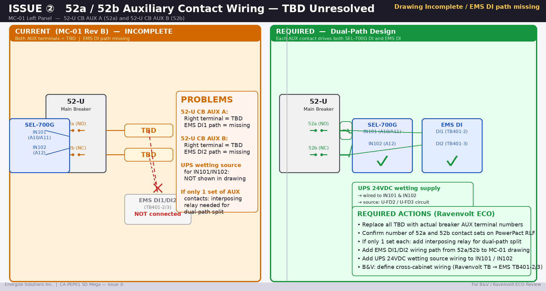
Item 2 — Incomplete Wiring: 52-U Auxiliary Contact Assignment (TBD Resolution Required)
Finding
Drawing MC-01 shows the following auxiliary contact connections:
52-U CLOSED AUX "A" (52a, Normally Open):
    Left side:  U-DCP2 → U-DCP2-1 → 52-U CB AUX A
    Right side: TBD — CB AUX A — TBD
    → Connected to: SEL-700G IN101 (A10/A11) via SYS-700G-A10

52-U CLOSED AUX "B" (52b, Normally Closed):
    Left side:  U-DCP2-1A → 52-U CB AUX B
    Right side: TBD — CB AUX B — TBD
    → Connected to: SEL-700G IN102 (A12) via SYS-700G-A12
Both auxiliary contact connections show TBD at the breaker terminal end. The actual terminal designations on the modified Schneider PowerPact RLF have not been assigned in the drawings.
Additionally, our technical review has identified that the project's control architecture requires 52a and 52b signals to be delivered to two independent destinations:
Destination 1: SEL-700G IN101 / IN102
               (Already shown in MC-01 — partially complete)

Destination 2: EMS DI1 / DI2 (TB401-2 and TB401-3)
               (Not shown in any current drawing)
If the modified PowerPact RLF provides only one set of 52a and one set of 52b contacts, an interposing relay will be required to create two independent signal paths.
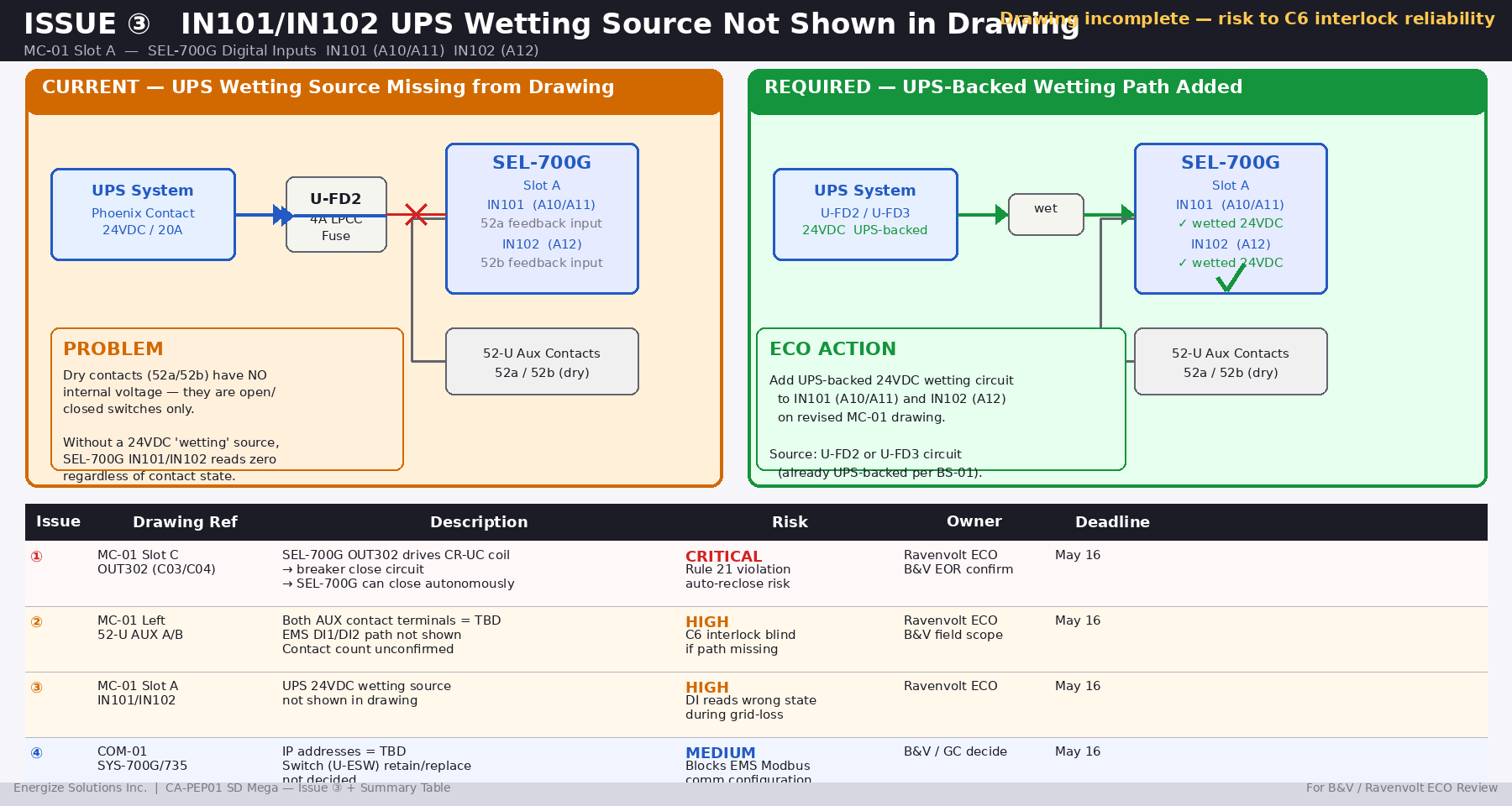
DI Wetting Requirement
The technical review annotation on MC-01 notes:
"Should be wetted with 24Vdc Supply from the UPS"
This is correct per IEC/NEC practice — dry contacts require an external DC voltage source for the digital input to register correctly. The current drawings do not show the 24VDC wetting source wired to IN101/IN102. This must be added to the revised MC-01.
The wetting supply must be UPS-backed (from U-FD2 or equivalent) to ensure breaker status remains readable during grid-loss conditions.
Requested Actions
From Ravenvolt:
Action 2a: Replace all TBD designations on 52-U CB AUX A and B
           with actual terminal numbers from the PowerPact RLF
           modification specification.

Action 2b: Confirm the number of independent 52a and 52b contact
           sets provided by the modified breaker.
           If only one set each:
           → Add interposing relay to MC-01 for contact multiplication
           → Show both signal paths: SEL-700G and EMS DI

Action 2c: Add 24VDC wetting source wiring to IN101 and IN102
           on revised MC-01. Source must be UPS-backed (U-FD2
           or U-FD3 circuit recommended).
From B&V:
Action 2d: Define and document cross-cabinet wiring:
           Ravenvolt 52a contact → EMS TB401-2 (DI1)
           Ravenvolt 52b contact → EMS TB401-3 (DI2)
           Include in field wiring scope / as-built drawings.
Requested completion: May 16, 2026
Item 3 — Protection Function Scope: Written Confirmation Required from B&V EOR
Background
In your email dated March 11, 2026, you proposed that voltage and frequency protection functions (ANSI 27, 59, 81O/81U) may not be required on the SEL-700G, based on the BESS operating in charge-only mode during grid-connected operation.
We understand the operational reasoning. However, we are unable to finalize the .RDB configuration based on an operational assumption alone, for the following reasons:
Regulatory basis for requiring 27/59/81:
California Rule 21 (Section H) and IEEE 1547-2018 (Sections 6.4–6.5) require voltage and frequency protection on all grid-connected energy storage interconnection systems. These requirements apply to the interconnection protection scheme as a system, independent of the DER's operating mode at the time of a grid anomaly.
Specifically, consider the following failure scenario: if the BESS PCS control fails and the unit begins discharging unexpectedly while grid-connected, the absence of ANSI 27/59/81 protection means there is no relay-level mechanism to detect islanding or voltage/frequency deviation. Under this condition, the SEL-700G would not issue a trip, and the BESS could continue energizing a de-energized section of the SDG&E distribution network — creating a direct safety hazard for SDG&E line crews.
Impact on .RDB development:
The SEL-700G .RDB file contains the protection setting database. The file must be finalized with either:
- Confirmed setpoints for ANSI 27/59/81 (if enabled), or
- Written engineering basis confirming omission, accepted by SDG&E
Without this confirmation, we cannot complete P3.2 (.RDB Configuration File Preparation), which is on the critical path for SDG&E final approval submission.
Confirmed settings to date:
ANSI 32 (Reverse Power):
  3PWR1P = 0.1% of utility transformer kVA
  PWR1T  = −WATTS (reverse direction)
  PWR1D  = 2.0 seconds
  Status: Confirmed per your March 11, 2026 email

ANSI 81R (ROCOF):
  Threshold: To be confirmed by EOR
  Status: Required, setpoint pending

ANSI 25 (Sync Check):
  Phase angle delta max: 5°
  Frequency delta max: 0.1 Hz
  Voltage delta max: 5%
  Status: Required for close authorization

ANSI 27/59/81O/81U:
  Status: PENDING EOR WRITTEN CONFIRMATION
Requested Action
Please arrange for the B&V Engineer of Record or designated PE (licensed in California) to provide written confirmation of the following:
For project CA-PEP01 SD Mega, are ANSI 27 (Undervoltage), 59 (Overvoltage), 81O (Overfrequency), and 81U (Underfrequency) protection functions required to be enabled on the SEL-700G?
Additionally, please formally assign a licensed protection engineer (PE) to this project if one has not yet been designated, as SDG&E's April 24, 2026 feedback explicitly requires EPC protection engineer involvement for final approval.
Energize can support implementation of the protection settings into the configuration package after receiving written direction from B&V's EOR. However, Energize is not acting as the Engineer of Record and will not certify final protection settings. Final protection setting approval, engineering justification, and SDG&E acceptance remain the responsibility of B&V's EOR / licensed PE.
Requested by: May 12, 2026
Item 4 — Network Configuration: IP Address Assignment and Switch Decision Required
Finding
Drawing COM-01 (Communications) shows:
SYS-700G IP Address: TBD
SYS-735 IP Address:  TBD
Subnet Mask:         TBD

U-ESW (Moxa EDS-205, 5-port unmanaged switch):
GC Annotation: "GC needs to decide if this unmanaged switch
               is required, or if direct Cat6 Ethernet is
               sufficient based on site distance/conditions"
The EMS Control Panel requires static IP addresses for both SEL-700G and SEL-735 before Modbus TCP communication can be configured and tested. This is a prerequisite for EMS commissioning.
Requested Actions
Action 4a: B&V/GC to assign static IP addresses for:
           - SYS-700G (SEL-700G)
           - SYS-735 (SEL-735)
           - EMS Control Panel ETH-1 and ETH-2 ports
           - U-ESW (if retained)
           Provide subnet mask, gateway, and port assignments.

Action 4b: GC to confirm whether U-ESW (Moxa EDS-205)
           is retained or replaced with direct Cat6 connections.
           This decision affects EMS ETH-1/ETH-2 physical routing.

Action 4c: Ravenvolt to update COM-01 replacing all TBD
           entries with confirmed IP addresses.
Requested by: May 16, 2026
Energize will configure EMS Modbus TCP communication based on the final IP plan provided by B&V / GC. Energize is not responsible for site network design, cable routing, cybersecurity policy, or final IT approval.
Summary of All Action Items
| Item | Action | Owner | Deadline |
|---|---|---|---|
| 1a | Correct OUT302 label on MC-01 | Ravenvolt (ECO) | May 16 |
| 1b | Disconnect OUT302 from CR-UC coil | Ravenvolt (ECO) | May 16 |
| 1c | Establish EMS-only close path for CR-UC | B&V + Ravenvolt (ECO) | May 16 |
| 1d | Verify/correct U1-01 wiring consistency | Ravenvolt (ECO) | May 16 |
| 2a | Replace TBD with actual breaker aux terminal numbers | Ravenvolt (ECO) | May 16 |
| 2b | Confirm 52a/52b contact sets; add interposing relay if needed | Ravenvolt (ECO) | May 16 |
| 2c | Add UPS-backed 24VDC wetting source to IN101/IN102 | Ravenvolt (ECO) | May 16 |
| 2d | Define cross-cabinet 52a/52b wiring to EMS DI1/DI2 | B&V field scope | May 16 |
| 3a | Written confirmation: ANSI 27/59/81 enable/disable + setpoints | B&V EOR (PE) | May 12 |
| 3b | Assign ROCOF (81R) setpoint | B&V EOR (PE) | May 12 |
| 3c | Formally assign licensed PE to project | B&V PM | May 9 |
| 4a | Assign static IP addresses for all network devices | B&V / GC | May 16 |
| 4b | Confirm U-ESW retain or replace decision | GC | May 16 |
| 4c | Update COM-01 with confirmed IP addresses | Ravenvolt (ECO) | May 16 |
Schedule Impact
For reference, the .RDB configuration file (Phase 3 Item P3.2) cannot be started until Items 1, 2, and 3 are resolved. Given the EMS hardware is expected to arrive on site in late May, resolution of all items by the dates above is on the critical path for commissioning.
Delays beyond May 16 will directly impact commissioning start date and, consequently, the SDG&E final approval submission timeline.
Please confirm receipt of this communication and advise on the timeline for each item. We are available for a technical call at your convenience to walk through any of the above in detail.
Best regards,
Andy Gong
Founder & Chief Systems Architect
Energize Solutions Inc.
📞 +1 (832) 598-7388
✉️ andy.gong@energizeos.com
🌐 energizeos.com